Please Note: Shipments to the United States may experience delays because of the new regulations and interruptions due to the inspection at the U.S. customs. We appreciate your understanding and patience

A drone operates within turbulent aerodynamic environments and congested RF spectra. Its onboard sensors capture high-frequency disturbances, structural vibrations, and intermittent satellite-signal availability. An inertial navigation system (INS) fuses these heterogeneous inputs into a continuous, high-integrity state estimate of the aircraft’s position, attitude, and motion. For UAV operators, this enables more stable control-loop performance, improved gimbal pointing accuracy, and robust navigation continuity during periods of GNSS degradation or outage.
An INS estimates the UAV’s attitude (roll, pitch, and yaw/heading), position, and velocity by fusing high-rate inertial measurements from gyroscopes and accelerometers with periodic GNSS updates, often supplemented by magnetometer and barometric data. The inertial sensors provide immediate response to motion, while GNSS observations constrain long-term drift in the inertial solution. This integration yields stable, continuous navigation states that remain reliable through aggressive maneuvers, wind-induced disturbances, and short-duration GNSS dropouts or multipath disruptions.
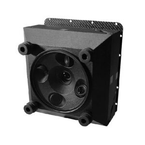
Inside the unit are triads of gyroscopes and accelerometers, typically complemented by a magnetometer for heading estimation and a barometric sensor for altitude smoothing. The INS outputs high-rate attitude data along with lower-rate navigation solutions such as position, velocity, and altitude, as well as diagnostic information including status flags, covariance estimates, and solution-quality indicators. Many UAV-oriented systems also support dual-antenna GNSS heading, which provides stable and drift-free yaw estimation even during low-dynamic flight regimes where magnetometer readings can become noisy or unreliable.
Inertial sensors drift over time because small bias and scale-factor errors integrate into growing position and attitude errors. GNSS measurements, on the other hand, can exhibit noise, jumps, and outliers caused by multipath, interference, or brief signal blockages. The sensor-fusion filter models the error characteristics of each sensor and statistically weights their contributions. When GNSS observations are reliable, the filter uses them to constrain the INS drift. When GNSS quality degrades, the system relies more heavily on the inertial propagation to maintain continuity until clean satellite updates become available again.
Mapping missions require tightly controlled roll and pitch angles to maintain consistent image geometry for photogrammetric stitching. Infrastructure inspection often occurs near metal structures, reflective surfaces, and dense RF clutter, where GNSS performance can degrade or become intermittent. BVLOS operations require systems that fail gracefully, without sudden loss of attitude, heading, or navigation continuity. Across all of these scenarios, an INS reduces uncertainty, stabilizes the aircraft’s state estimates, and keeps the mission on a predictable, controllable trajectory.
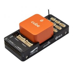
Begin by defining the required attitude and position accuracy for your mission profile. Determine whether you need dual-antenna GNSS heading to achieve stable yaw performance, especially during low-dynamic flight. Evaluate available interfaces—such as UART, CAN, Ethernet, and PPS—for telemetry, configuration, and precise time synchronization. Confirm that compatible drivers exist for your autopilot stack (Pixhawk, ArduPilot, Cube) and verify the maximum update rates those drivers can reliably handle. Finally, assess the unit’s mass and power consumption to ensure it fits within your platform’s payload and endurance constraints.
Mount the INS rigidly and as close to the aircraft’s center of gravity as practical, and document its installation orientation for use in the configuration parameters. Place the GNSS antennas where they have an unobstructed sky view and ensure low-loss, interference-free cable routing. When available, enable PPS or time-mark inputs so camera triggers, navigation logs, and telemetry streams remain tightly synchronized. Before the first flight, verify sensor-axis alignment and heading on the ground, then conduct controlled GNSS-masking tests to confirm the system maintains stable attitude and navigation continuity during brief signal degradations.
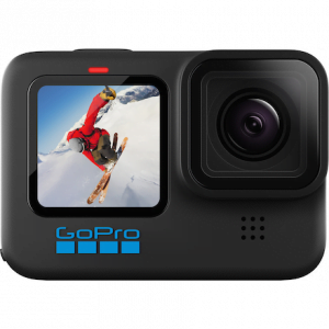
Ready to compare models? Explore inertial navigation systems for drones. Build the full stack with GNSS RTK modules, IMU sensors, Pixhawk, and Cube autopilots, UAV mapping cameras and Ground control software.
No account yet?
Create an AccountNeed help?