Please Note: Shipments to the United States may experience delays because of the new regulations and interruptions due to the inspection at the U.S. customs. We appreciate your understanding and patience

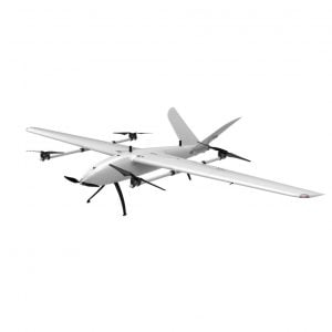
Drone’s Inertial Navigation Systems (INS) helps aircraft, drones, ground robots, and marine platforms navigate when satellite signals are weak or unavailable. By integrating accelerometer and gyroscope data from an IMU, an INS estimates position, velocity, and attitude starting from a known state. The challenge is drift – tiny sensor errors and modeling imperfections that accumulate over time and degrade accuracy.
So how does an INS stay accurate as minutes turn into hours? This unified article delivers the entire content in one continuous sequence, with your original text preserved and new sections added to close content gaps.
Understanding accuracy over time starts with separating short‑term behavior from long‑term stability. Short term covers seconds to a few minutes; long term spans many minutes to hours.
Short‑term accuracy is dominated by sensor noise and high‑frequency disturbances. Contributors include angle and velocity random walk, quantization, sample‑to‑sample jitter, and vibration coupling. Proper mechanical isolation and filtering reduce these effects. In flight logs this appears as small jitter in attitude and velocity estimates.
Long‑term accuracy depends on how biases and scale‑factor errors evolve. Bias instability, temperature sensitivity, misalignment, and sensor aging make the solution drift when unaided. Even at rest, uncompensated biases integrate into position and attitude errors over time.
Pilots feel short‑term noise as twitchy attitude control; survey and navigation tasks are limited by long‑term drift. Designing the system requires treating both regimes differently.
Warm up the IMU to a stable temperature based on the device datasheet
Use rigid mounting with vibration isolation and consistent screw torque
Calibrate biases and scale factors in controlled conditions and re‑check after major temperature changes
Use aiding sources when available -GNSS RTK, barometer, magnetometer, visual or wheel odometry
Apply motion constraints and zero‑velocity updates during stops to reset drift
Log raw IMU and estimator states to evaluate performance across missions
Compute Allan variance on stationary IMU data to identify noise density, bias instability, and random walk terms. Use these to tune filter process noise and predict drift over mission duration.
An INS uses a cluster of sensors – accelerometers to measure specific force and gyroscopes to track rotation. Starting from a known position and attitude, it integrates these measurements forward in time to estimate where it is and how it is moving. Because it does not rely on external signals, INS works underwater, indoors, through tunnels, and in space. The trade‑off is drift as small errors compound.
Even precise sensors are imperfect. Temperature changes, noise, vibration, numerical integration, and slight misalignments introduce small errors that accumulate. Over time, the estimated position and attitude diverge from reality – the classic INS drift. The rest of this guide details proven ways to slow or reset that drift so accuracy is maintained across a mission.
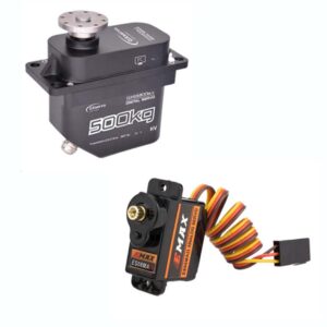
Use high‑precision IMU sensors
Aerospace‑grade IMUs exhibit lower bias and noise. Temperature compensation and stable timing further reduce initial error growth.
Calibration to Correct Bias and Alignment
Calibration is like stretching before a workout – it ensures everything is aligned and ready to perform. When an INS starts up, it’s calibrated to correct for biases and alignment errors.
Sensor Bias Correction: Over time, sensors develop a small bias – a consistent error in measurement. Calibration helps account for this.
Alignment Check: Ensuring the IMU’s axes are perfectly aligned with the vehicle’s reference frame reduces systematic errors.
Regular calibration is essential, especially for systems that experience frequent environmental changes or vibrations.
Real‑Time Error Modeling and Correction
No sensor is perfect, but error modeling can predict and compensate for imperfections. By understanding how a sensor typically behaves under certain conditions, the INS can correct its calculations on the fly.
Bias Drift Modeling: By measuring how sensor bias changes over time, the system can anticipate and adjust for drift.
Random Walk Compensation: Algorithms help smooth out the random noise that can creep into sensor readings.
Error modeling is a continuous process, where the system “learns” and corrects itself in real time.
Apply advanced estimators
Use filters such as extended or unscented Kalman filters with consistent process and measurement noise. Employ zero‑velocity or zero‑angular‑rate updates when conditions allow.
Fuse with external information
Blend IMU with GNSS, vision, lidar, radar, barometer, and magnetometer to provide absolute references and constrain drift.
Leverage external aids and maps
Use geomagnetic maps, known landmarks, or preloaded environment models to recalibrate in GNSS‑denied areas.
Build redundancy and health monitoring
Multi‑IMU setups, cross‑checks, and integrity monitoring detect faults early and improve reliability.
Track emerging technologies
Quantum sensors and learning‑based estimators promise better long‑term stability as they mature.
When an INS runs for minutes or hours, aiding sources keep drift in check. The right mix depends on platform, environment, and required accuracy.
Loosely coupled -INS and GNSS run as separate estimators while the INS consumes GNSS position and velocity updates. Simple and robust but less effective with few satellites.
Tightly coupled – A single filter fuses raw GNSS measurements with IMU states. Works with fewer satellites and provides smoother navigation through partial outages.
Deeply integrated -IMU data feeds the GNSS tracking loops. Delivers the best continuity in harsh environments at higher complexity.
Multi‑constellation and multi‑band receivers for better geometry and faster convergence
SBAS or differential corrections for sub‑meter performance
RTK for centimeter‑level accuracy when a base or network is available
PPK when offline processing is acceptable for survey‑grade results
Antenna best practice – clear sky view, rigid mount, ground plane, correct lever arm
Magnetometer for long‑term heading stability where interference is controlled
Barometer for smooth altitude aiding and climb‑rate consistency
Visual odometry or SLAM with cameras in GNSS‑denied spaces
Wheel odometry or kinematic constraints on ground robots
Lidar odometry or depth sensors in feature‑rich environments
Ranging or beacon systems such as UWB indoors or in urban canyons

Zero‑velocity updates during planned stops to reset accumulated errors
Zero‑angular‑rate updates on stable mounts to reduce gyro bias effects
Vehicle‑specific constraints for aircraft, multirotors, and wheeled platforms
Forward‑backward smoothing in post‑processing to improve long runs
Time‑sync IMU and GNSS and calibrate the lever arm between antenna and IMU
Keep the antenna away from EMI sources and spinning propellers
Log raw IMU, GNSS observations, and estimator states for diagnostics
Validate performance on repeatable routes across temperatures and payloads
A structured calibration and test routine prevents long‑term drift and makes accuracy predictable. Focus on thermal characterization, bias and scale‑factor calibration, alignment, and verification with repeatable tests.
Allan variance separates short‑term noise from long‑term instabilities. Record stationary IMU data at the nominal sample rate for at least one to three hours - longer for lower‑noise sensors. Compute Allan deviation versus averaging time.
A slope near −1⁄2 indicates white noise and sets noise density
A flat region indicates bias instability and shows the best stability time
A slope near +1⁄2 points to rate random walk
Use these terms to tune filter process noise and predict drift over mission duration.
Warm the device from cold to hot and back while logging continuously. Build temperature‑bias models for gyros and accelerometers, then enable temperature compensation in firmware. Allow a short warm‑up until temperature stabilizes before missions.
Perform multi‑position static calibration for accelerometers and zero‑rate calibration for gyros. Use precise rotations or a turntable to estimate scale factors and misalignment. Repeat after major mechanical changes or when the temperature range expands.
Mount the IMU rigidly and measure boresight angles between IMU, vehicle frame, and antenna or camera frames. Measure the lever arm between IMU and GNSS antenna and enter it in the estimator to avoid long‑term position and attitude drift.
If using a magnetometer, run hard‑iron and soft‑iron calibration in a low‑interference area. Keep high‑current wires, motors, and steel parts away from the sensor and validate heading stability in hover and forward flight.
Repeat a standard test route with static segments and gentle turns
Insert planned stops for zero‑velocity updates and compare drift before and after
Compare against a trusted reference when available - RTK, motion capture, or surveyed points
Review logs for estimator consistency, innovations, and temperature spread
Document calibration dates, temperatures, and results for traceability
This checklist turns accuracy theory into day‑to‑day practices for field teams.
Power on early so the IMU reaches a stable temperature before arming
Verify time sync between IMU, GNSS, and flight controller
Confirm GNSS status, correction source if used, and antenna visibility
Load the correct calibration profile for the expected temperature range
Use a rigid mount with vibration isolation appropriate to the vehicle
Keep the IMU away from motors, power wiring, and magnetic materials
Tighten fasteners consistently and document orientation to avoid misalignment
Measure and enter lever arms between IMU, GNSS antenna, and payload sensors
Set consistent sampling rates and avoid clock drift
Tune process noise using Allan‑variance results and field logs
Enable aiding sources that match the mission - GNSS, magnetometer, barometer, visual or wheel odometry
Configure motion constraints and zero‑velocity updates where applicable
Plan routes with clear sky where possible and avoid reflective structures
Use takeoff hovers or pauses to let filters converge
For indoor or urban canyons, prefer visual or lidar odometry and beacon aids
Define acceptable drift windows and fallback procedures for GNSS outages
Calibrate wheel‑odometry scale and slip detection
Apply zero‑velocity updates during stops and at docking stations
Use heading aids - magnetometer or visual yaw - when turns are slow or stationary
Log raw IMU, GNSS observations, estimator states, and temperature
Review residuals and innovations to spot bias changes or poor aiding
Compare repeated routes to track long‑term stability and calibration drift
Archive firmware versions, calibration dates, and mounting changes
Twitchy attitude usually indicates vibration or aggressive filtering -reduce vibration and review filter bandwidth
Growing position error at rest points to uncompensated biases - recalibrate and verify warm up
Inconsistent heading suggests magnetic interference - relocate the sensor or rely on non‑magnetic aids
| Method | Description | How it helps | Examples |
|---|---|---|---|
| Precision sensors | High‑quality IMUs with low noise and bias | Reduces initial drift and error accumulation | Aerospace‑grade IMUs |
| Calibration | Bias, scale‑factor, and alignment correction | Ensures accuracy from the start and after changes | Multi‑position accel, zero‑rate gyro |
| Error modeling | Predict and compensate sensor imperfections | Compensates bias drift and random walk | Bias‑drift models, noise adaptation |
| Advanced algorithms | Estimators with consistency checks and updates | Minimizes real‑time errors and smooths drift | EKF or UKF, ZUPT or ZARU |
| Sensor fusion | Combine INS with external references | Provides absolute updates and redundancy | GNSS, vision, lidar, radar |
| External aids | Maps and fields for recalibration where GNSS is weak | Offers positional updates in denied areas | Geomagnetic maps, UWB |
| Redundancy | Additional sensors and integrity monitoring | Cross‑checks data and detects faults | Multi‑IMU setups |
| Emerging tech | Next‑generation sensors and learning methods | Improves long‑term stability over time | Quantum gyros, ML estimators |
What is the difference between accuracy and stability in an INS
Accuracy describes how close the estimate is to truth at a given moment; stability describes how that accuracy behaves as time passes, especially during long periods without external updates.
Why does an INS drift even when the platform is stationary
Uncompensated biases in gyros and accelerometers integrate into attitude and position over time. Temperature changes and sensor aging also contribute.
How does GNSS aiding help maintain long‑term accuracy
GNSS provides absolute position and velocity updates that correct INS drift. Tighter integration works better in weak‑signal situations.
What warm up time is advisable before using an INS on a drone
Allow the IMU temperature to stabilize according to the datasheet and your thermal tests. This reduces bias shifts after takeoff.
How does mounting and vibration isolation impact accuracy
Poor mounting couples vibration into the IMU and increases noise. Rigid, well‑isolated mounting reduces short‑term jitter and prevents misalignment.
What is Allan variance and why is it useful
It separates noise processes across time scales, letting you estimate noise density, bias instability, and random‑walk terms to tune filters and predict drift.
How can I reduce drift during GNSS outages on UAV missions
Use motion constraints, zero‑velocity or zero‑angular‑rate updates, visual or lidar odometry, and plan pauses to let estimators re‑converge.
What data should I log to diagnose accuracy issues over time
Log raw IMU, GNSS observations, estimator states, innovations, and temperature. Review repeat missions to detect calibration drift.
Maintaining INS accuracy over time is about smart sensor selection, disciplined calibration, robust estimation, and the right aiding strategy for your mission and environment. Combine these practices and you will see predictable, stable performance from takeoff to landing - even when GNSS is not always there to help.
No account yet?
Create an AccountNeed help?